
Measure Forces in Members of. 86 shows the types of boundary conditions for displacements.
1 5 Internal Forces In Plane Trusses Engineering Libretexts
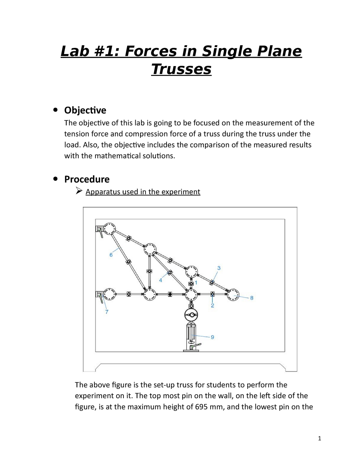
Loading device Figure 1.

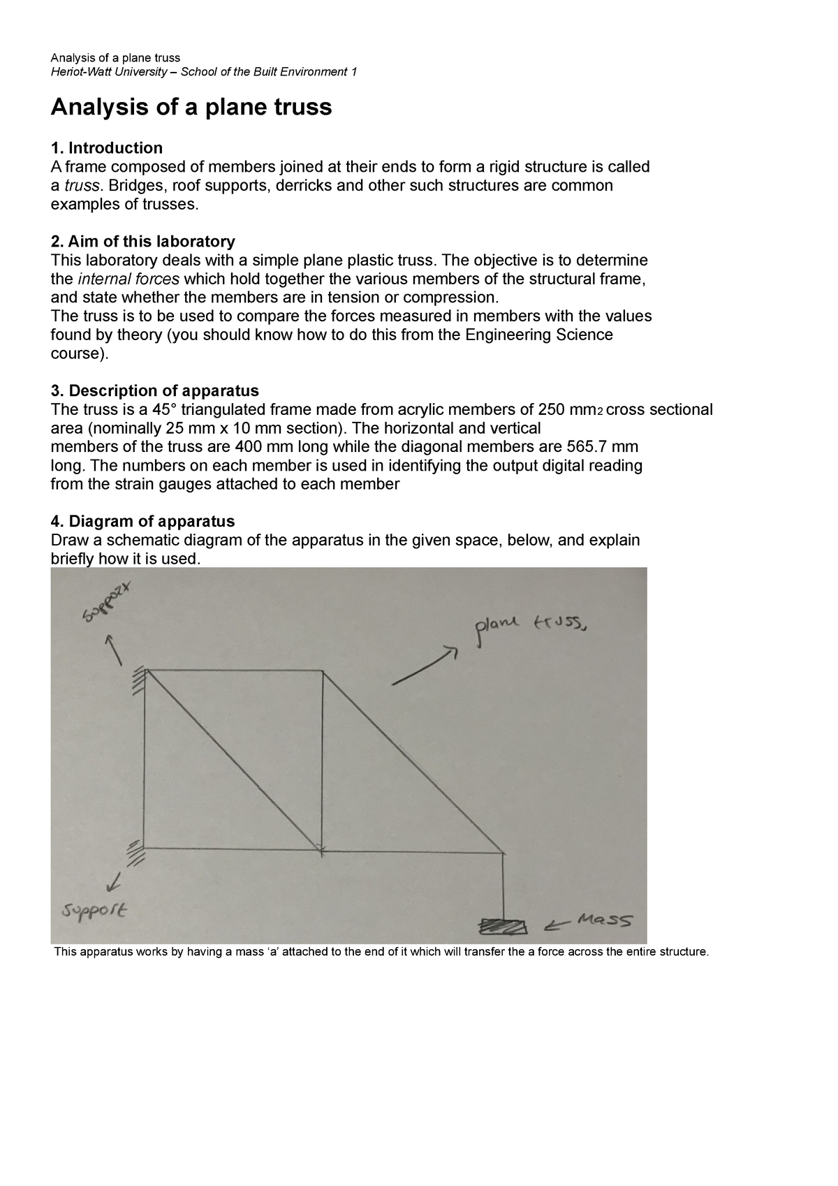
. The basic structure of a truss is shown in figure 1 below. 6 MATERIALS LAB CEMB 121 MEL Date Name Student ID. Truss ie a truss whose mem-bers are subjected only to axial forces.
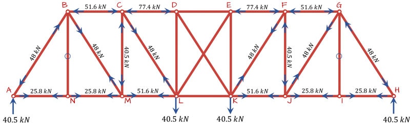
ë 5 7 L ë 5 8 L10000 0 B Shear load. 1 A Warren truss with members having a force gauge fixed to it. Their main advantage is that they can span large distances using a minimum amount of material.
Test Data Results for Laboratory Experiment No. What you will do in the lab. A member lies in one plane or two dimensional plane.
F force in member N. ë 5 7 L F ë 5 8 L10000 Figure 1. A Cross-sectional area of member m2.
Trusses can be defined as structural elements that are long and assembled by connecting them at the end. Test Data Results Table 61. This type of truss is seen in a framed roof consisting of rafters and a ceiling joist and in other mechanical structures such as bicycles and aircraft.
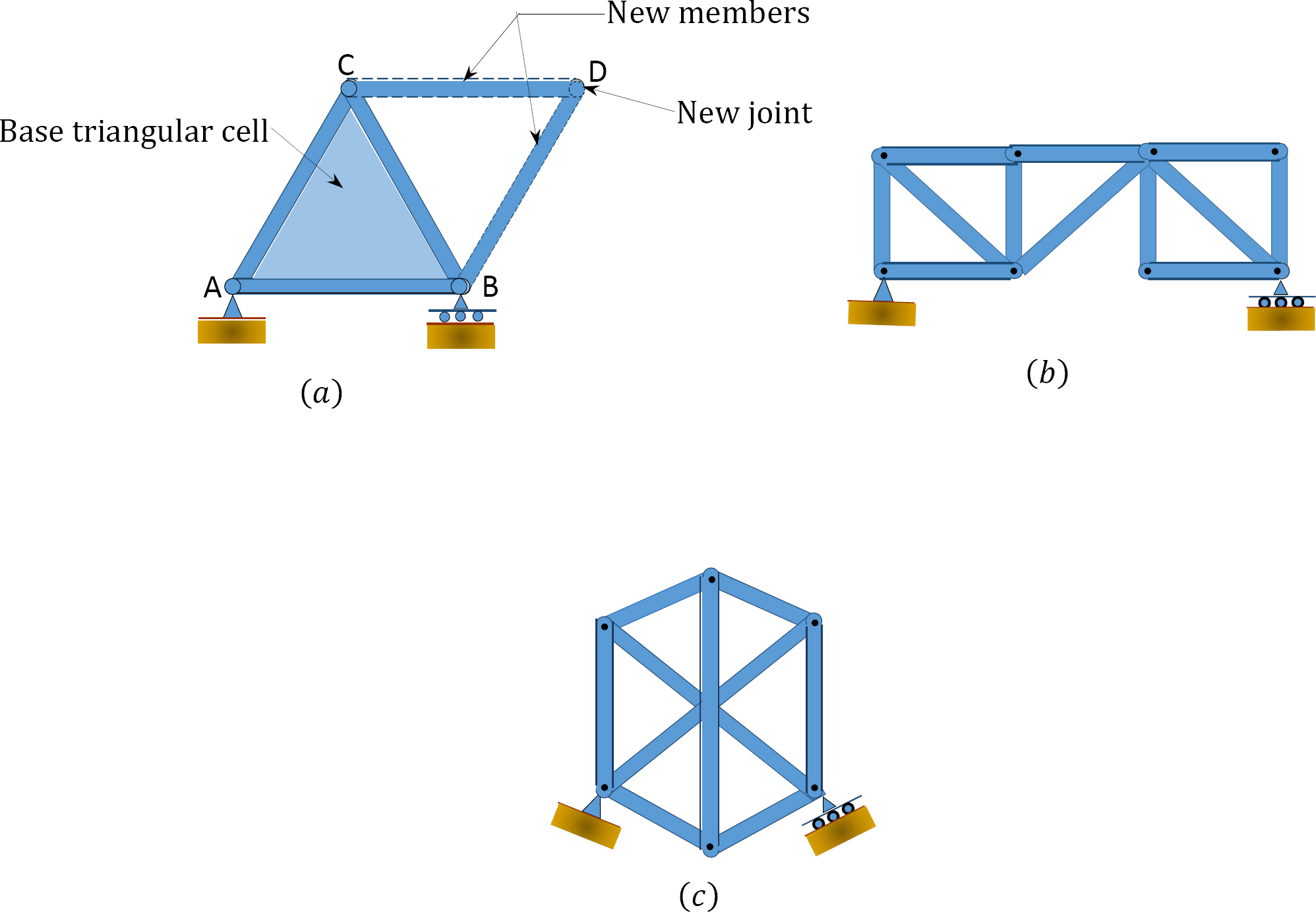
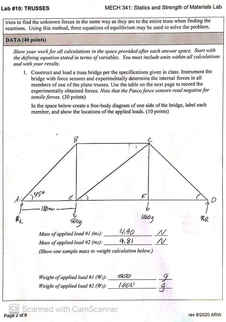
The members of a plane truss are subjected to axial compressive or tensile forces. The purpose of this lab is to construct and test a single plane truss in a rigid reaction frame and record reaction forces when a load is applied. It is a planar truss which begins with triangular element and can be expanded by adding two members and joints.
The assumptions in the analysis of plane trusses include the following. Forces in plane truss see the report discussion what are mentionef there write an complete and correcr discussion about this report. 20 Theory Trusses are used extensively in structural engineering applications.
This type of truss is seen in a framed roof consisting of rafters and a ceiling joist and in other mechanical structures such as bicycles and aircraft. Primary Forces member axial forces determined from the analysis of an ideal truss. ZERO FORCE MEMBERS The deformation of statically determinate plane truss can be determined using Virtual Work Method.
The truss that will be investigated in this experiment is a statically determinate planar truss. A plane truss is defined as a two-dimensional framework of straight prismatic members connected at their ends by frictionless hinged joints and subjected to loads and reactions that act only at the joints and lie in the plane of the structure. All the members lie on a plane while the loads carried by the trusses are only concentrated forces.
Trusses used widely in most construction projects. A truss is one of major type of engineering structures. 1 Division 5N 1 POLITEKNIK SULTAN SALAHUDDIN ABDUL AZIZ SHAH C4003 CIVIL ENGINEERING LAB.
ì 5 7 L ì 5 8 L1000 C Bending moment. In Class Wednesday 112608 Overview A three-dimensional truss is tested under transverse loading and the load-deflection characteristics and the internal barmember strains are measured. Forces In Plane TRUSS Objective.
Please make it as soon as possible. You will choose one of the strain gages and use the P-3500 strain indicator to measure the strain. 40 Observation and results.
10 Introduction2 20 Theory. Because of the stability of this shape and the methods of analysis used to calculate the forces within it a truss composed entirely of triangles is known as a simple truss eg. A planar determinate truss can have only.
Dial gauge readings. 2 A screw jack for applying load to the truss. Tuesday 111808 Laboratory Work.
The total number of unknowns includes the forces in b number of bars of the truss and the total number of external support reactions r. V2 Compare in a table the experimental and theoretical member forces for the 500-N load case. To determine the forces in members of a plane truss.
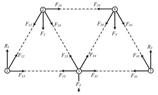
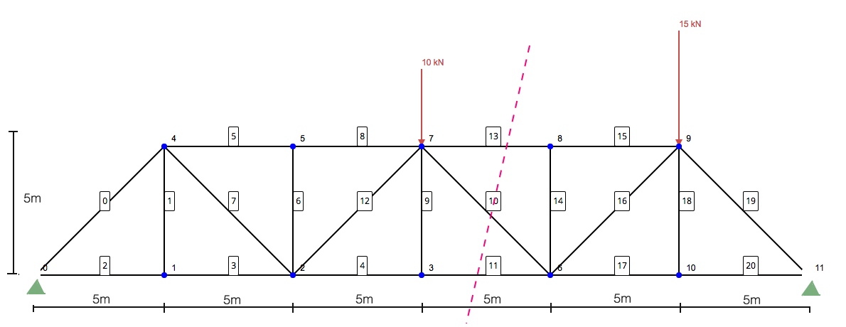
In this lab report it was investigated that the Kinetic and Static friction force between a steel plank and other materials ie. Deviations from the idealized forces ie shear and bending forces in a truss member. Schematic of plane truss under consideration.
If three members form a truss joint for which two of the members are collinear the third member will be a zero-force member provided no external load or support reaction acting at the joint. Truss configuration and loading device. The use of trusses in construction.
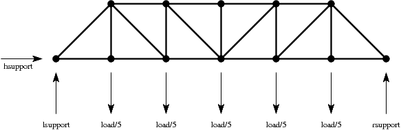
The plane truss in Figure 1 is analyzed using finite element analysis FEA for three load cases. A plane truss is one where all the members and joints lies within a 2-dimensional plane while a space truss has members and joints extending into 3 dimensions. If large secondary forces.
Lab report for engineering lab 2 laboratory 2force in redundant truss table of content forces in redundant truss title principles objectives apparatus. Two loads will be tested and all internal forces must be recorded. Show these member forces on a sketch of the truss.
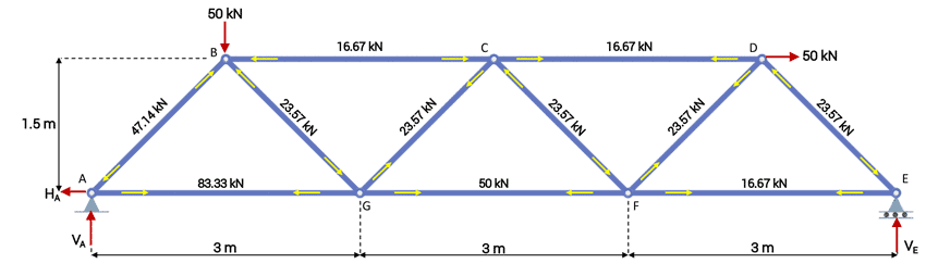
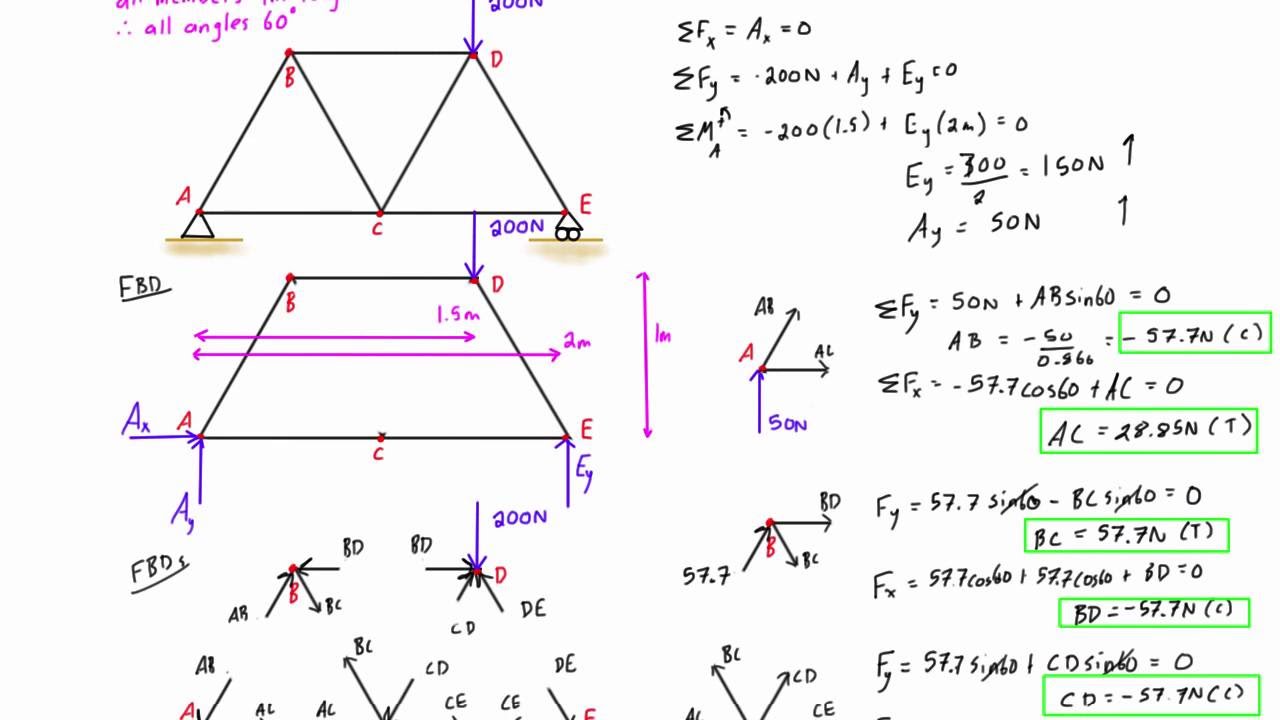
Our focus will be on primary forces. Following the same dimensions and loading the forces acting in truss will be solved mathematically. Knowing the axial force in a member the normal strain in the member is 1 where.
The Truss In Class Session. SM3 Title of Experiment. Remember to subtract the strain measured in P 0 load case from the loaded values.
Classification based on co-planar trusses 1. 1706245 AffiliationYear 1School of Engineering Date Performed on 07-Dec-17 Understanding the behavior and the analysis of the truss -----resolving forces and moments Abstract Table of contents. Members deformations are small and negligible.
If three members form a truss joint for which two of the members are collinear the third member will be a zero-force member provided no external load or support reaction acting at the joint. To determine the forces in members of a plane truss. E Youngs modulus of member Pa.
They consist of straight members where none of the member is continuous through a joint. Since the truss members are all straight axial force members lying in the same plane the force system acting. These include in buildings such things as scaffoldings bridges towers roofs to name but a few.
Members are straight and are subjected to axial forces. Members of trusses are connected at their ends by frictionless pins. REPORT V1 Convert the strain readings for the five load cases into member forces.
ES196Statics structure Truss lab report Name IDChen Jiawei Darren Student ID. Wednesday-Friday 1119-2108 Laboratory Report Due. Plane or Planar truss.
30 Apparatus and methods. FORCES IN PLANE TRUSS EXPERIMENT 4 DKA 5A OBJECTIVE. 10 Objective To determine the forces in members of a plane truss.
It consists of members jointed together at their ends to form 3D structure. Forces in plane truss lab report. If only two members form a truss joint and no external load or support is applied the members must be zero-force members Case 2.
Doing The Math Analysis Of Forces In A Truss Bridge Lesson Teachengineering

Pdf An Apparatus To Measure Force In A Simple Truss System
Assignment 4 Solving Linear Equations The Pratt Truss Bridge
Truss Analysis Tutorial Method Of Joints And Sections Degreetutors Com
Mechanics Of Materials Lab 1 Lab 1 Forces In Single Plane Trusses Objective The Objective Of Studocu
The Analysis Of Trusses
Truss Analysis By Method Of Joints Worked Example 1 Youtube
Solving Truss By Method Of Sections Skyciv Engineering

Truss Analysis By Method Of Joints Explained Youtube
Solved Objective Demonstrate The Effects Of External Chegg Com

1 5 Internal Forces In Plane Trusses Engineering Libretexts

Structures Zero Force Members In Truss Engineering Science Structural Analysis Force
1 5 Internal Forces In Plane Trusses Engineering Libretexts
Analysis Of A Plane Truss Laboratory Report Analysis Of A Plane Truss Heriot Watt University Studocu
Structural Analysis Case Study Tutorial Degreetutors Com

1 5 Internal Forces In Plane Trusses Engineering Libretexts

Sc 05 Plane Truss Inclined Support Inclined Force Local Axis Youtube

Structures Zero Force Members In Truss Engineering Science Structural Analysis Force

Analyzing A Simple Truss By The Method Of Joints 12 Steps With Pictures Instructables


